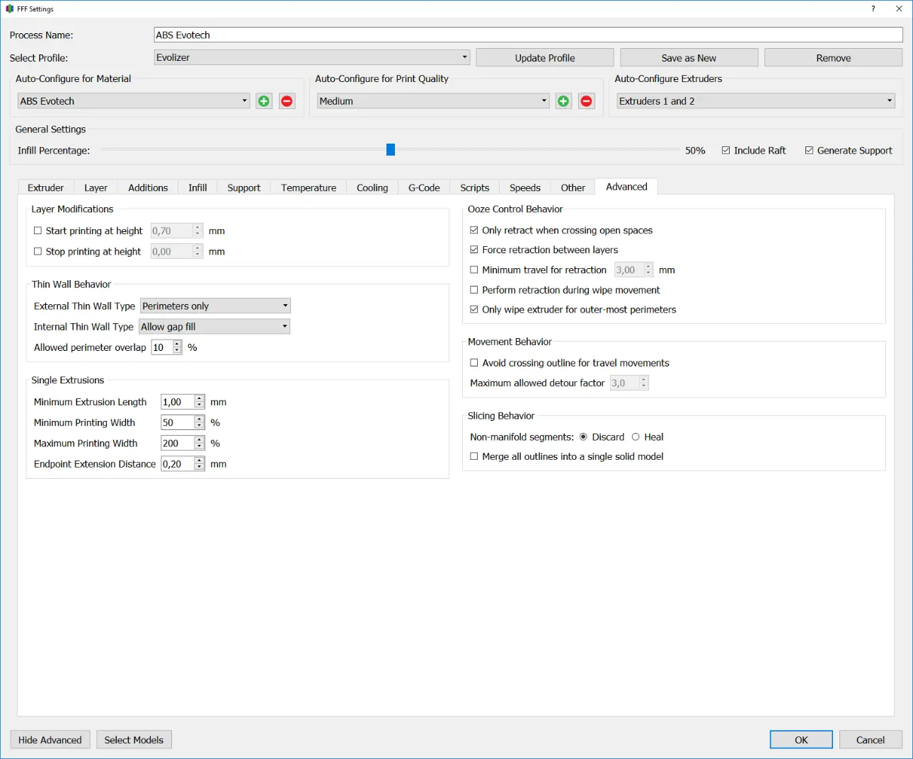
Layer Modifications
The settings in this area can be used to start or end a process in the Z direction from a set height. This can be useful to split a model in the Z direction by simply stopping printing at a set height, or to print the component with different settings, e.g. layers of different thicknesses.
Start Printing at height
Specifies the Z height from which the process begins.
Simplify3d starts printing at this height, it is up to the user to ensure that another process takes care of the layers below.
Stop Printing at height
Specifies the Z height at which the process ends.
Thin Wall Behavior
Thin Wall Behavior determines the behavior of the printer when producing wall thicknesses that are smaller or, inconveniently, larger than the Extrusion Width.
External Thin Wall Type
External Thin Walls are wall thicknesses that are thinner than the Extrusion Width. In this sub-point you can decide how the slicer handles the corresponding areas of the component.
Perimeters only
In this setting, walls are only built from perimeters; areas that are thinner than the extrusion width are not printed. This is usually the default setting.
Allow Single Extrusion Walls
In this setting, areas that are thinner than the extrusion width are created with so-called single extrusions. To do this, the feed of the filament is reduced and the extruded material is pulled along with the nozzle. In this way, wall thicknesses that are smaller than the nozzle diameter can also be achieved.
If the wall thickness varies, the feed is dynamically adjusted so that the wall thickness corresponds to that of the model. However, the change from perimeter to single extrusion does not happen dynamically; here the extruder stops and starts a new line.
Internal Thin Wall Type
External Thin Walls are wall thicknesses that are thinner than the Extrusion Width. In this sub-point you can decide how the slicer handles the corresponding areas of the component.
Perimeters only
In this setting, the resulting gap is filled with a single line parallel to the perimeters. This can be a lot wider or narrower than the extrusion width.
Allow single extrusion fill
The pillar width indicates the side length of the square base of the pillar. For low objects, this setting can be set to 10 mm. When printing taller objects, the base area should be larger so that the Prime Pillar does not detach from the build platform during printing.
Allow gap fill
In this setting, the resulting gap is filled using Gap Fill. Gap fill is a structure similar to infill, but independent of the settings made for the infill.
Allowed Perimeter Overlap
Specifies the percentage that perimeters are allowed to overlap. Higher values result in perimeters being used to fill thin internal walls before using single extrusions or gap fill.
Single Extrusions
In this area you can control the behavior of the single extrusions from the Thin Wall Behavior area.
Minimum Extrusion Length
Specifies the minimum length that a single extrusion must have in order to be printed. This value should be chosen relatively low, otherwise defects can occur in the component.
Minimum Printing Width
Specifies the Minimum Percentage of Extrusion Width that a Single Extrusion can have.
Maximum Printing Width
Specifies the maximum percentage of extrusion width that a single extrusion can have.
Endpoint Extension Distance
Specifies the length by which the ends of each Single Extrusion are extended to better weld with the rest of the part. A good guideline for this is half the nozzle diameter.
Ooze Control Behavior
This checkbox ensures that retracts are only carried out when the print head moves over open areas, i.e. crosses perimeters.
Only retract when crossing open spaces
Specifies the maximum percentage of extrusion width that a single extrusion can have.
Force retraction between layers
With this checkbox, retracts are carried out at shift changes.
Minimum travel for retraction
Specifies the minimum idle length that the print head must travel before a retract is performed.
Perform retraction during wipe movement
This checkbox ensures that retracts are carried out during the wipe movement.
Perform retraction during wipe movement
This checkbox ensures that retracts are carried out during the wipe movement.
Only wipe extruder for outer-most perimeters
This checkbox ensures that wipe movements are only used for the outermost perimeter, which saves printing time, especially for large models with multiple perimeters
Movement Behavior
Avoid crossing outline for travel movements
This checkbox ensures that the print head, before it crosses a perimeter, takes a different path that does not cross any perimeters. This is particularly useful with flexible filaments, as they usually experience very strong oozing
Maximum allowed detour factor
This factor indicates how much longer the detour can be in order not to cross any perimeter. For example, a factor of 2 means that the detour can be twice as long.
Slicing Behavior
Non-manifold segments
This option determines how to handle bad areas in the model. Here you can decide whether faulty areas should simply be deleted or whether Simplify3d should try to repair them automatically.
Merge all outlines into a single solid model
This option takes the outermost lines of the model and fills the entire layer. This makes it possible to repair some faulty models, but you lose all features inside the component (e.g. holes).