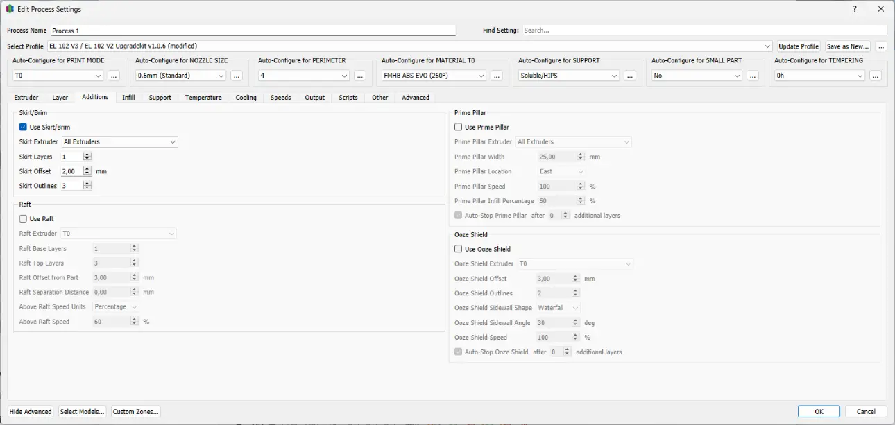
Use Skirt/Brim
A skirt or brim is an additional strip that is printed around the component in the first layer.
Skirt Extruder
This option determines the extruder with which the skirt or brim is printed.
Skirt Layers
Here you can determine how many layers the skirt or brim will be printed over. If using a Skirt, this setting should be left at 1. When using materials that shrink enough to tear the brim, 2 or more coats may be used. However, it should be noted that the thicker the brim becomes, the more difficult it is to remove it without damaging the component.
Skirt Offset from Part
This determines how far away the skirt or brim is printed from the component. One speaks of a skirt when this strip is placed a few millimeters away from the component. This is usually used to build up pressure in the nozzle before manufacturing the actual component begins. A brim is connected to the component. This is used to increase the adhesion surface of the component on the build platform.
Skirt Outlines
This option sets the number of outlines. The width of the skirt or brim results from the number of lines as well as the extrusion width from the layer tab and the modifications made in the first layer area. This should be particularly taken into account when using very thin or very thick nozzles, as the brim will then be particularly narrow or wide.
Use Raft
The raft is a substructure on which the component is then printed. There are various applications for the raft. Typically, a raft is used to improve the adhesion of the component to the build platform, or to create a precisely flat layer on which the component is then printed. In addition, the raft can also be used if the component in the first layer has a large cross-section and the adhesion of the material to the construction platform would become so great that the component could no longer be removed without being destroyed. Since the lower layers of the raft consist of several thick strips that are placed parallel to each other at some distance, they are easier to remove after printing. A raft consists of two different types of layers. The upper layers are printed finer than the lower ones, and the density of the infill in these layers can also be controlled. The lower layers are printed more coarsely and have a fixed infill density.
Raft Extruder
This option specifies the extruder used to print the raft. When using a Brim at the same time, the same extruder should be chosen to ensure sufficient adhesion between the webs.
Raft Top Layers
This option sets the number of top layers of the raft. In order to obtain a stable base, at least three layers should be applied here. A smaller number of layers saves material and printing time, but may not be able to withstand the stress caused by the cooling component. When using fine nozzles, it makes sense to increase the number depending on the material used. If you don't want any upper layers but only the roughly printed layers of the Raft Base Layers, the Raft Top Layers can also be set to zero.
Raft Base Layers
This option sets the number of bottom layers of the raft. These layers are printed thicker and slower than the Raft Top Layer. Therefore, these layers require a lot of time and material. Since the setting of more than
Separation Distance
The separation distance indicates the distance between the top layer of the raft and the bottom layer of the component. In this way, the adhesion of the component can be controlled directly. As a guideline, half the layer height can be used as the minimum value and the entire layer height as the maximum value, but the exact values depend on the material used, the primary layer height and the nozzle diameter.
Raft Top Infill
The Raft Top Infill indicates how densely the Raft Top layers are printed. In order to get a nice first layer on the component, 100% should be selected here. If you want to reduce the adhesion of the component to the raft, you can reduce the value as much as necessary.
Above Raft Speed
Above Raft Speed sets the speed at which the first layer of the component is printed onto the raft. Slower speeds result in better grip.
Use Prime Pillar
The Prime Pillar is a cuboid with a square base that is printed first in each layer after a nozzle change. This option was originally intended for printers that use two different filaments in the same nozzle, but this option also has advantages for printers with two nozzles. Since the Prime Pillar is printed after a nozzle change, it can be used to build up pressure in the new nozzle and maintain a clean starting point on the component.
Prime Pillar Extruder
The Prime Pillar Extruder option can be used to specify which extruders use the Prime Pillar. When printing with two nozzles, this option should be set to “All Extruders” as the slicer then decides which nozzle is used in which layer.
Pillar Width
The pillar width indicates the side length of the square base of the pillar. For low objects, this setting can be set to 10 mm. When printing taller objects, the base area should be larger so that the Prime Pillar does not detach from the build platform during printing.
Pillar Location
The Pillar Location specifies the position of the prime pillar relative to the object.
Speed Multiplier
The Speed Multiplier indicates at what percentage of the Primary Print Speed the Prime Pillar is printed. Especially for taller objects, this value should be chosen slightly lower to avoid the Prime Pillar becoming detached from the building platform.
Use Ooze Shield
The Ooze Shield is a shell that is printed some distance around the component. Since using two nozzles can cause some material to drip from the unused nozzle, this feature is used to wipe off the excess material before the nozzle comes into contact with the component.
Ooze Shield Extruder
This setting determines the extruder that will be used to print the Ooze Shield. Since the Ooze Shield only has a function during printing and is then thrown away, the extruder that is loaded with the cheaper material should be used here.
Offset from Part
The Offset from Part specifies the distance at which the Ooze Shield is printed from the component. A value of 5 -10 mm has proven useful here. The Ooze Shield should not be too far away from the component, otherwise filament can drip out of the nozzle on the way to the component, but not too close either, otherwise you risk fusing with the component.
Ooze Shield Outlines
This value determines the number of lines an Ooze Shield consists of per layer. Here a value of 2 has proven to be a good average between stability and material consumption.