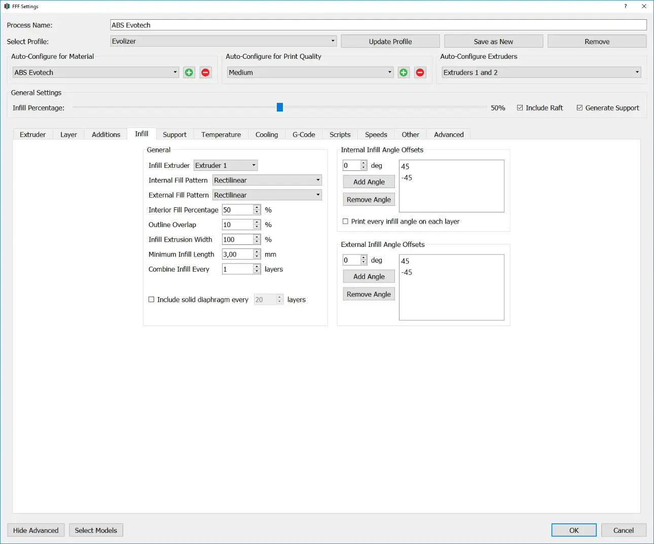
The filling of the component is set in the Infill tab. The filling density and the structure of the filling can be determined here. Choosing the right infill influences the printing time and the stability of the finished component.
General
Infill Extruder
This option specifies the extruder used to print the infill.
Internal Infill Pattern
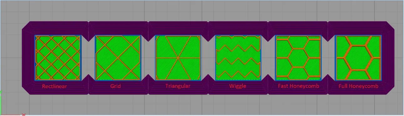
The Internal Infill Pattern defines the basic structure of the inner filling. The default pattern is Rectlinear. If more stable components are to be manufactured, the Triangular and Full Honeycomb patterns are a good choice. The Wiggle Pattern is only recommended for aesthetic purposes, as it increases the printing time the most and at the same time has the least stability.
Rectliniear
With the “Rectlinear” setting, the infill consists of parallel lines that are alternately oriented +45° and -45° to the x-axis with each layer.
Grid
The “Grid” infill structure is very similar to the “Rectlinear” setting. The difference here is that both the +45° and -45° paths are printed in each layer. This creates a wider-meshed network, but the structure itself is more stable.
Triangular
“Triangular” infill is a triangular filling structure. Here the tracks are laid at 0°, +60° and -60° in one layer.
Wiggle
The wiggle infill structure consists of zigzag lines that follow an imaginary guideline. The orientation set indicates the orientation of the guideline.
Fast Honeycomb
Fast Honeycomb is a honeycomb infill structure, but the full honeycomb structure is only printed every other layer, while a zigzag pattern, similar to the wiggle infill, is printed on top in the other layer.
Full Honeycomb
Full Honeycomb is a honeycomb infill structure. In contrast to Fast Honeycomb, a full honeycomb structure is printed in each layer and rotated by 120° in the next layer.
External Infill Pattern
The External Infill Pattern determines the structure of the “Top Solid Layer” and “Bottom Solid Layer”. The filling level is always 100%.
Rectlinear
With the “Rectlinear” setting, the infill consists of parallel lines that are alternately oriented +45° and -45° to the x-axis with each layer.
Concentric
Concentric means that the lines of the infill are concentric to the lines of the perimeter.
Interior Infill Percentage
The Interior Infill Percentage determines the degree of filling of the internal structure. Higher filling levels result in more stable components, but the printing time and material consumption increase. When using low filling levels, it should be taken into account that sufficient top solid layers are used, as these tend to tear open when bridging large open areas. If a fully filled component is to be manufactured, filling levels of 98-99% are a good choice. At 100%, the problem is usually that too much material is used and it moves upwards, which causes the next layer to be smeared and, in the worst case, the nozzle collides with the component and the corresponding motor skips steps, resulting in an offset in the component.
Outline Overlap
The outline overlap indicates how much of the extrusion width the infill and perimeter overlap. The default value here is 10%. When using large diameter nozzles, this value should be increased to avoid holes in the component.
Infill Extrusion Width
Specifies the ratio of the extrusion width of the infill to the extrusion width of the perimeter. The default value here is 100%. For materials with high shrinkage, increasing this value can help avoid stress cracks between layers.
Minimum Infill Length
Specifies the minimum length an infill line must have to be printed. The standard value here is around 3 mm. This setting avoids unnecessary travel of the print head, but if the value is chosen too high, it can happen that the component does not receive infill in places where it would actually be necessary.
Combine Infill Every … layers
Specifies how thick a layer of infill is in relation to the primary layer height. The value entered here, multiplied by the primary layer height, results in the layer height of the infill. Increasing this value is particularly advantageous when the perimeter and infill are manufactured with different nozzle diameters, as you get both the detail of a fine nozzle for the perimeter and the speed of a wide nozzle for the infill.
Include Solid Diaphragm every … layers
With this checkbox, a layer of the infill with 100% fill level is printed every few layers. This increases the stability of the component but also increases the printing time and material consumption.
Internal Infill Angle Offsets
The angles of the infill are defined in this area. Simplify3d stores standard values for each infill type here, which can be further adapted by the user for special applications.
Print every Infill angle on each layer
With this checkbox all previously defined angles are printed in each layer. This setting should only be used with low fill levels as the overlapping lines can extend beyond the layer height.
External Infill Angle Offsets
In this area the angles of the infill of the top and bottom solid layers are defined. Simplify3d stores standard values for each infill type here, which can be further adapted by the user for special applications.