Support material is required in 3D printing to produce overhanging structures. A distinction is made between break away support and solution support.
Break Away Support is a support structure that is loosely connected to the component and can be removed mechanically after printing. The material used for this can be identical to the model material.
Soluble Support is firmly attached to the component and is chemically dissolved after printing. For this it is necessary that the part of the support structure that is in contact with the component consists of a different material than the model material.
Some of the support settings are also accessible from the preview window, and there is also the option to define your own support structures in addition to the automatically placed supports
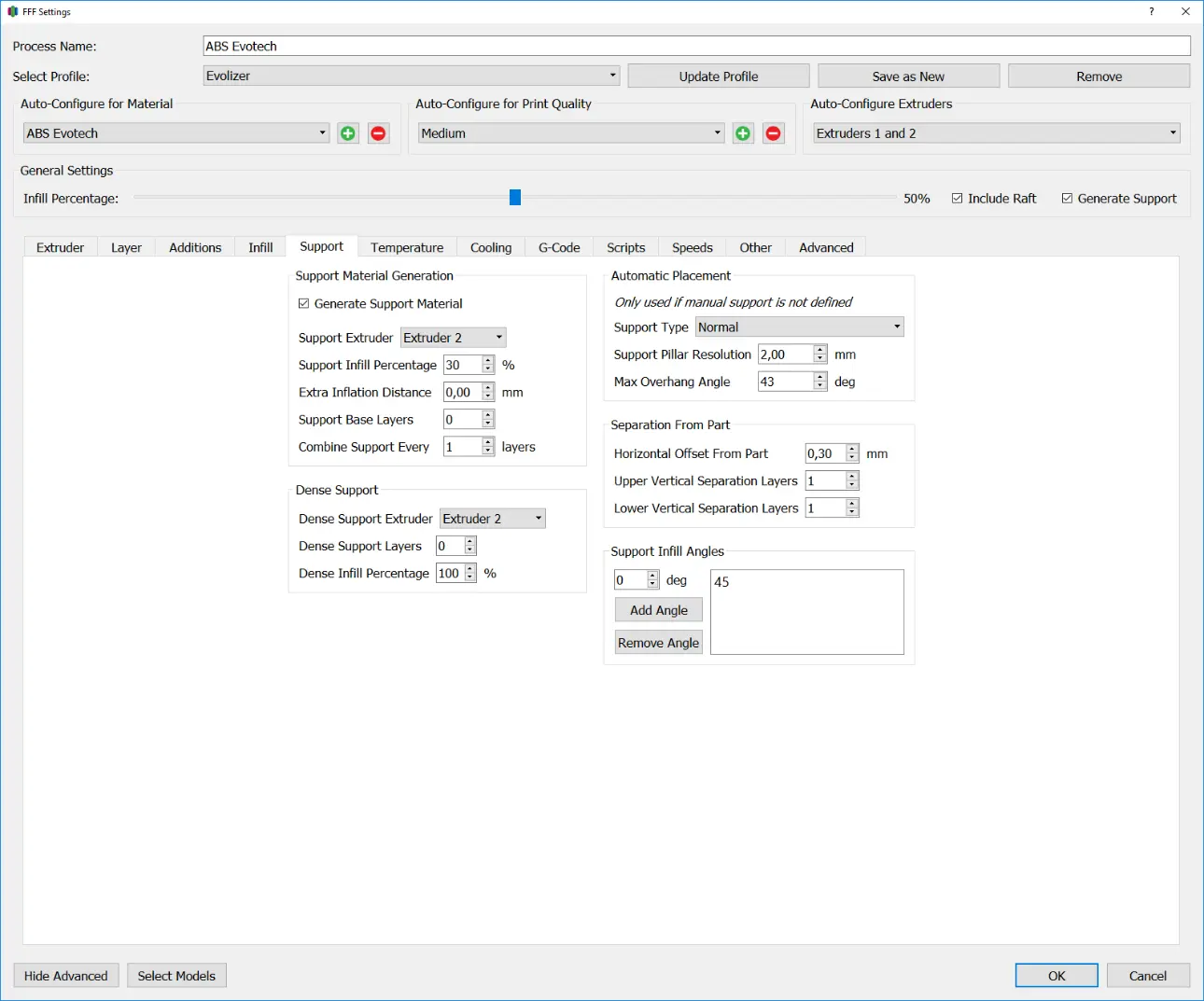
Support material generation
Generate Support Material
This setting determines which extruder will be used to print the support structure.
Support Infill Percentage
The Support Infill Percentage indicates the density of the support structure. Denser support structures provide more stability and support during printing, but are more difficult to remove afterwards.
Extra Inflation Distance
This option specifies how far beyond the component the support structure should be printed. This is particularly helpful with break away support as it makes removing the support structure easier. Useful values for the Extra Inflation Distance are 1 to 2 millimeters. Attention: With a combination of high inflation distance values and thin-walled components, the support structure may protrude through the outer wall
Support Base Layers
Support Base Layers are layers that are printed underneath the support structure to increase its adhesion and stability. This is particularly necessary when tall and thin support structures are to be manufactured. As a rule, one layer is enough.
Combine Support Every … Layers
The value entered here multiplied by the Primary Layer Height results in the thickness of a layer of the support structure. The default value for this option is 1. If you want to shorten the printing time, the value can be set to 2.
The use of higher values is only advisable if the model and support structure are manufactured with nozzles of different thicknesses. (Example: The model is printed with extruder 1, with a 0.4mm nozzle and the support structure with extruder 2, with a 0.7mm nozzle) The same rule of thumb applies here as with the primary layer height: the layer thickness should be between 25 and 75 % of the nozzle diameter.
Dense Support:
Dense Support is a dense support structure that is printed above the normal support structure. This can be used to create a better surface for the component lying on it with a filling level of 60 to 80% or, with a filling level of 100% and the use of the second extruder, to create a chemically detachable connection between the normal support structure and to create the component
Dense Support Extruder
Specifies the extruder used to print the dense support structure.
Dense Support Layer
This option specifies the number of layers executed in dense support structure.
Dense Infill Percentage
Dense Infill Percentage indicates the degree of filling of the dense support structure.
Automatic Placement:
The settings made here only come into effect if no user-defined support structures have been generated in the preview window.
Support Type
Normal:
With this setting, a support structure is calculated everywhere on the component, both those areas that originate from the build platform and those that attach to the component. This setting creates a support structure wherever it is needed, but the attachment points can leave visible artifacts on the component surface.
From Build Platform only:
This setting only generates those support structures that have a connection to the build platform. This does not create any visible artifacts on the component surface, but overhangs that would require a support structure are eliminated
Support Pillar Resolution
The Support Pillar Resolution indicates the resolution of the grid with which the support structure is calculated. A high resolution (low millimeter value) ensures that all overhangs are captured, but it can happen that the support structures are too thin and break off during the printing process. A low resolution (high millimeter value) may not capture all overhangs, but support structures will be wider and more stable.
Different resolutions can be combined when calculating the support structure.
Max. Overhang Angle
Specifies the angle of the overhang from which a support structure is generated. 0° means vertical, 90° means horizontal. Based on experience, the sensible value here is around 43°. Higher values mean fewer support structures.
Separation from Part
Horizontal Offset from Part
Specifies the distance that the support structure maintains in the xy direction to the component. If the value is too low, the support structure will stick to the component and leave visible markers. A value that is too high can result in the support structure being unnecessarily far away from the component and overhangs that need to be supported not receiving any support. A good guideline is half the nozzle diameter.
Upper Vertical Separation Layers
Specifies the number of layers between the top layer of the support structure and the part. The distance in the z direction results from this value and the primary layer height.
When using soluble support material, this value should be zero.
To use break-away support, this value should be one. When using thin layer thicknesses (around 0.1 mm and less), it may be advisable to further increase the value for materials with strong layer adhesion if the support structure is difficult to remove.
Lower Vertical Separation Layers
Specifies the number of layers between the bottom layer of the support structure and the component. The distance in the z direction results from this value and the primary layer height.
Support Infill Angles
Specifies the angle of the support structure lines. Only one angle should be used for break-away support, as the support structure can then be removed more easily. However, if this is to be solved chemically anyway, two angles that are rotated by 90° to each other can also be used. This results in a more stable structure and more surface area, which speeds up dissolution.